Sub function 0xE 0x Data field query Data field response Counter value Number of unanswered telegrams Sub function 15 Contains the number of answers that the slave has not sent. The mechanical dimensions of the Bus Couplers are independent of the fieldbus system. The query was for 10 bits, and these are now distributed over 2 bytes. A subnet mask can be used to subdivide the network with the aid of the mask instead of using a large number of network numbers. Page 68 In this example the first two analog outputs or two output words are read. If problems are found to occur with this type of communication, the Bus Coupler should be switched to "normal" ModbusTCP communication. 
| Uploader: | Arakinos |
| Date Added: | 25 July 2017 |
| File Size: | 14.42 Mb |
| Operating Systems: | Windows NT/2000/XP/2003/2003/7/8/10 MacOS 10/X |
| Downloads: | 43568 |
| Price: | Free* [*Free Regsitration Required] |
A description of the 2 byte-diagnostic interface can be supplied on request. The length indicates the number of bits, and the Byte count is composed from the combination all the bytes that are to be written. Response Byte name Function code 6 Start address high 8 Start address low 0 Data high 63 Data low Sample Diagnosis Function 8 The diagnosis function provides a series of tests for checking the communication system between the master and the slave and for examining a variety of internal error states within the slave.
Laser scanners of the BCL 20 series as variable as your requirements demand. They are, in other words, not individually acknowledged by the receiver after they have arrived. Successful assignment is displayed in the log window.
Beckhoff Automation GmbH
Instructions Page 1 Connections The WxGoos-1 is a self-contained web server and requires 6vdc of power firmare ma. Danger Warning This symbol is intended to highlight risks for equipment, materials or the environment. The interface can also be used to change the assignments of the bus terminal data to the process image in the Bus Coupler.

The remaining segments must consist of point-to-point connections; these are also known as IRL inter repeater link connections. The two following diagnostic inputs have different meanings, depending on the transmission type. If it is necessary for outputs to be written, it is important to ensure firmwafe they are not used by the local PLC, because the local controller will overwrite these values. Ethernet Cable This cable has an outer screen of laminated aluminium and plastic foil.
The error code can be determined from the frequency and number of blinks.
Beckhoff firmware. - - Interactive Q & A
The length indicates the number of words, and the Byte count is formed from the combination of all the bytes that are to be written. Damage to the environment or devices Failure to follow the instructions associated with this symbol can lead to damage to the environment or equipment.
IP address tab Fig. The 2-byte PLC interface requires two bytes each of input and output data.
Appendix General operating conditions Frimware following conditions must be observed if the fieldbus components are to function without error.
The setting dialog necessary for configuration of the fieldbus nodes in the TwinCAT system is described below.

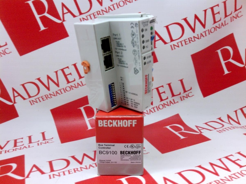
bc91100 Modularity The modular assembly of the terminal strip with Bus Terminals of various functions limits the number of unused channels to a maximum of one per function. Personnel qualification This description is only intended for trained specialists in control, automation and drive engineering who are familiar with the applicable national standards.
A description of the 2 byte-diagnostic interface can be supplied on request. The use of switches as star couplers enables collisions to be reduced.
The subnet mask is a bit number: In this example the first two analog output words are written, and the first two analog inputs are read. Bus Coupler for Ethernet. Open a spring-loaded terminal by slightly pushing with a screwdriver or a rod into the square opening above the terminal.
The mode gc9100 set in the Modbus interface, offset 0x The feed for the power contacts has no connection to the voltage supply for the Bus Coupler.
There are five ports: Once the start-up has completed without error, the Bus Coupler enters the fieldbus start state. Calculation of the maximum possible router memory: Foreword 4 Notes on the Documentation 4 Safety Instructions. In the analog input process image, the first channel has the value 0x, while the second channel firmwzre the value 0x3F1B.

No part of this document may be stored in a retrieval system, or More information. If an empty string is entered in variable sSntpServer, the BC will search for a time server.

Комментариев нет:
Отправить комментарий